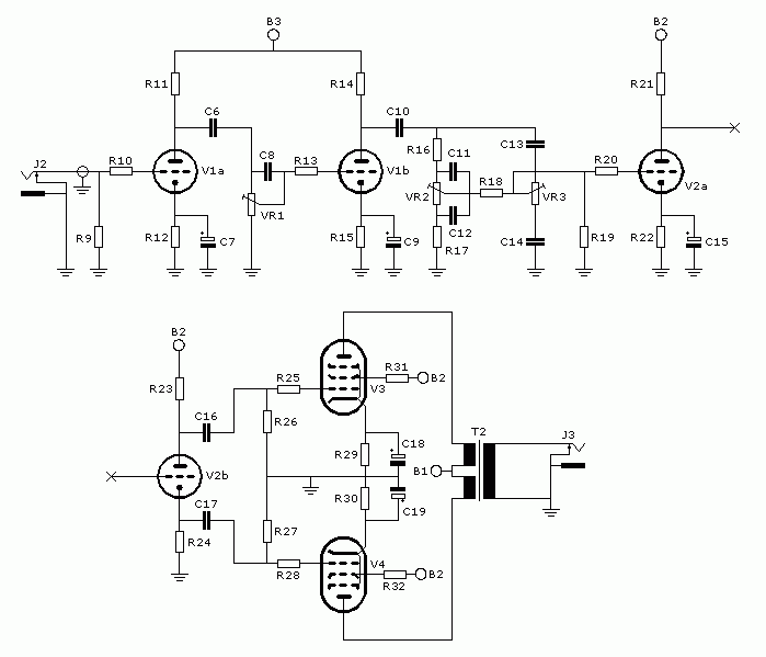
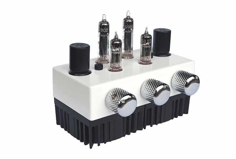
After finishing my class A subminiature amp I started his project. It features two preamp dual-triodes of type 6112 and 6021, a class AB 5902 pentode output stage and a conventional power supply. The idea for this amp came by browsing through an electronic vendors parts catalogue. On their toroidal transformer page they listed a series of transformers that when put next to each other exactly measure 11 cm. The same as a Hammond 1590 B enclosure. By this coincidence they can be seemlessly integrated as power and output transformer for a mini-amp.
Warning! This page describes circuits dealing with high possibly fatal voltages. Don't attempt to build the describes circuits unless you know how to follow appropriate safety procedures. If you don't know what I'm talking about now, then you should not attempt this project.
Biggest influence for the ampflifying circuit was the Orange OR80 amp from the early 1970s. It shares some of its features like the James tone stack (sometimes called a passive Baxandall tone stack) and the cathodyne phase inverter.
|
R9 R10 R11 R12 R13 R14 R15 R16 R17 R18 R19 R20 R21 R22 |
1M 15k 100k 820 39k 100k 820 100k 10k 180k 470k 39k 100k 680 |
R23 R24 R25 R26 R27 R28 R29 R30 R31 R32 VR1 VR2 VR3 |
22k 22k 5k6 220k 220k 5k6 1k 1k 33k 33k 500k log 500k log 500k log |
C6 C7 C8 C9 C10 C11 C12 C13 C14 C15 C16 C17 C18 C19 |
22n 630 V film 1u 16 V electrolytic 330pF 500 V ceramic 2u2 16 V electrolytic 22n 630 V film 470p 500 V ceramic 4n7 500 V ceramic 330p 500 V ceramic 3n3 500 V ceramic 2u2 16 V electrolytic 15n 630 V film 15n 630 V film 100u 25 V electrolytic 100u 25 V electrolytic |
V1 |
6112 dual-triode 6021 dual-triode 5902 pentode 5902 pentode 2x115 V to 2x7 V 10 VA toroidal mono audio jack mono audio jack |
To maximize the available gain and increase the signal to noise ratio early in the amp, a 6112 dual-triode is used for V1. It has an amplification factor of 70 and can reach in-circuit voltage gains of up to 55, in this regard making it comparable to a 12AT7 tube. For V2 a 6021 dual-triode is used for its higher current capability. This property makes it more suited in the cathodyne phase inverter.
VR1 is the gain control, the tone controls are VR2 for bass and VR3 for treble.
The two ouput tubes are Sylvania J.A.N. 5902 pentodes. They are cathode biased. Fixed-bias is not an option since there is no negative voltage source available. Maximum plate dissipation is 3.7 W, maximum screen dissipation 1 W and cathode current may not exceed 50 mA according to the Sylvania datasheet. Other manufacturers (Phillips, General Electric) give 4 W for the max. plate dissipation.
The output transformer is of the same type as the power transformer. It is a toroidal ("donut" style) 10 VA PCB mount transformer with two 115 V primaries and two 7 V secondaries with a no-load voltage of 8.5 V, so the plate-to-plate impedance ratio is 732:1 ((230 V / 8.5 V)^2). An 8 Ohm speaker gives a primary impedance of about 5.8 kOhm. To make a center tapped primary the high voltage lines are wired in series and the connection point is used as the center tap. Secondaries are parallel connected for maximum current capability.
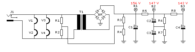
Contrary to my previous amplifier this amp uses a conventional transformer based power supply. The higher and less steady current demand of the class AB output stage made a switch-mode power supply hard to implement. In fact there are now two more tubes than in the previous amplifier, which makes board space even more of a problem. There is just not enough room for inductor and oscillator.
|
R1 R2 R3 R4 R5 R6 R7 R8 |
100R 100k 270k 270k 2k2 220k 220k 5k |
C1 C2 C3 C4 |
47u 350 V electrolytic 47u 100 V electrolytic 47u 100 V electrolytic 47u 350 V electrolytic |
BR T1 J1 |
B250S SMD bridge rectifier 115 V to 9 V 10 VA toroidal DC plug |
Power comes to this device through a home made 12 V AC wallwart transformer. In this I am using a 25 VA type of the same brand as the the other transformers. With this setup I get exactly 12.6 V on the input and 126 V after step-up transformation (under load).
Note that the power plug is not grounded, therefore the power connector must not touch the casing. The only earth reference is through the voltage divider for elevating the heaters. The heaters (and therefore also the power connector!) are elevated to about 80 V to rise the heater voltage above the cathode voltage. This prevents them of acting like a forward biased diode and effectively removes mains (50 Hz) hum being fed into the cathode.
Now some words about transformer selection. Size and type were already defined by the look I was going for, but the electrical properties were still to be specified. I wanted a DC voltage of about 165 V DC at the power tubes, which translates to roughly 117 V before the rectifier. From 12 V that means a voltage ration of 10. First impulse would now be to buy the 115 V to 12 V transformer. Wrong! Transformer secondary voltages are always given for rated current, which means the no-load voltage is considerably higher to allow for core and copper losses. In case of this transformer it's 14.6 V for the 12 V model, giving a voltage ratio of under 8. If this transformer was used, the rectified voltage would only reach 134 V (12 V * 8 * 1.41) without load connected!
The 9 V model has a no-load voltage of 11.0 V giving a ratio of 10.5. This gives an idle voltage of 176 V (12 V * 10.5 * 1.41). A connected load will lower this voltage further, my build measures 156 V for B1 at idle.
Capacitors C2 and C3 are used instead of one with higher voltage rating so that they could fit inside the enclosure. The voltage across them is balanced with resistors R6 and R7. The capacitors vary so much in capacity (often -30 % to +50 % for electrolytic capacitors) that their impedance divides the B2 voltage unequally, which may lead to overvoltage for one of the 100 V caps.
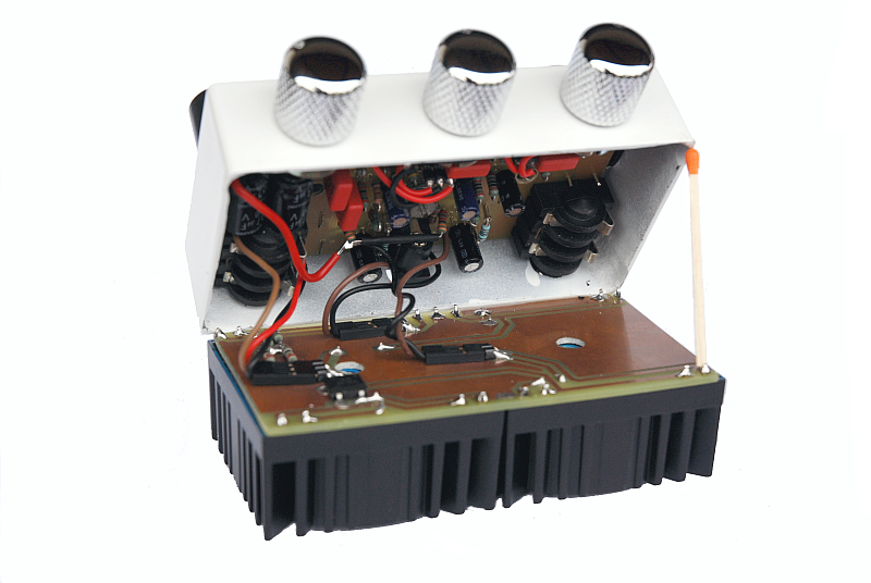
This amp consists of two printed circuit boards. One of them holds the transformers and does in fact replace the original aluminium cover. On this board there are also resistors R1 to R4 and the rectifier. It is secured to the case with two screw that fit into the transformer mounting holes.
Located on the main PCB are the tube sockets and all the rest of the components except for the tone stack which is soldered directly to the potentiometers.
As in the last amplifier the ground connection is made through a screw and nut glued to the case. All offboard connections are made using removable connectors. The main circuit board comes off the case after three screws (two for the casing, one for the board) and 5 plugs (three to the transformer board, two to the potentiometers) are removed.
The connection between the input jack and the first tube grid is made through a shielded cable (RG-174), mostly to keep 100 Hz noise out.
My only problem with this amps is that it gets very hot inside. I measured 60 °C at the casing of one of the power tube cathode bypass capacitors. It would probably be wise to use 105 °C electrolytic capacitors throughout the amp. Heat comes almost entirely from the output tubes. Don't even think about touching them, with their 450 mA heater current they get much hotter than the preamp tubes (300 mA heater). The power transformer only gets slightly warm.
Here is a link to the manufacturer of the specific transformers I used: Talema PCB Mount
2x115V  .
.
Click on a picture for a larger version.
I have recorded some samples of this amp using a strat-style guitar (all singlecoil pickups). The amp is plugged into the 10" speaker of a combo amp (half-open back). Recording is done through a Sennheiser microphone, a Soundblaster X-Fi and Audacity. The samples are normalized but otherwise unaltered.
Clean (347 kB) - gain at 9 o'clock, strat neck pickup
Distortion (652 kB) - gain at 12 o'clock, strat bridge pickup
Distortion (839 kB) - full gain, strat bridge pickup
Please send questions and comments to electronics@jjs.at.